Introduction
Traditionally, audio effects such as filters, reverbs, delays, distortions, etc., have been implemented using analog circuits. Within the last 15-20 years digital effects have grown substantially in viability and popularity due to the increasing ubiquity of low cost, high performance microprocessors. Digital platforms offer a lot of benefits over their analog counterparts, such as
- Slimmer form factors
- One device fulfilling the role of many effects
- Saving and recalling parameter presets
A typical drawback of digital processing is the latency experienced for live use. Depending on the internal signal chain and types of effects being implemented, latency can be a big issue, especially if you are chaining multiple digital devices together.
Summary
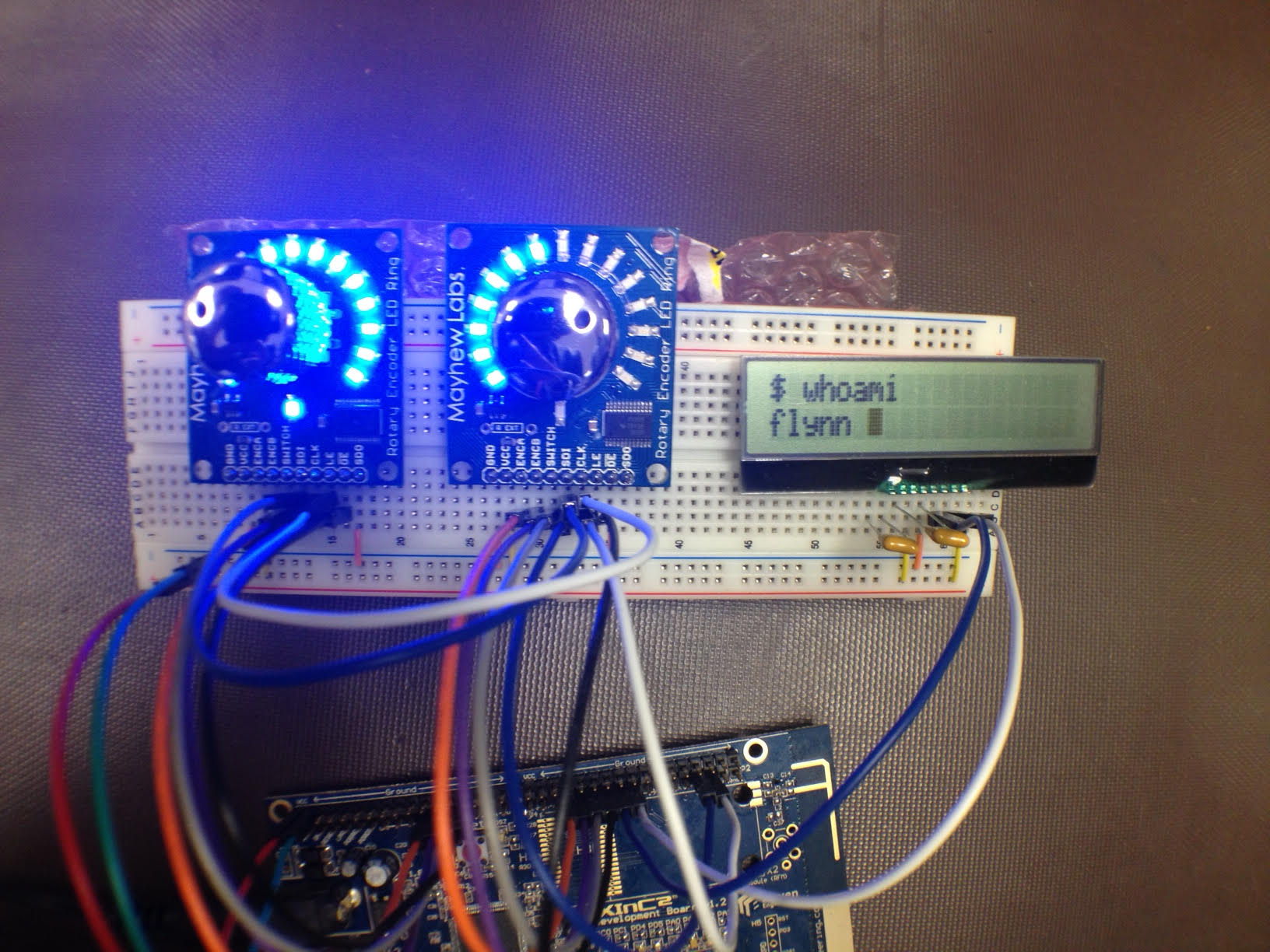
For a university capstone design project, I and two other members designed and implemented a digital guitar effects processor from scratch. The goal was to create a minimal audio effects processing platform for guitars with a high quality audio signal chain. The device consisted of three major stages; the hardware input, the digital signal processing stage, and the hardware output. This device was implemented with Eleven Engineering’s XInC2 microprocessor, a multithreaded processor capable of performing finite impulse response (FIR) filters with its vector processing unit (VPU). The operation of the device was controlled through two rotary encoders and user feedback was provided with two corresponding LED rings and an LCD screen.
I was responsible for the firmware on the microprocessor, which controlled the digital preamplifier via SPI, interfaced with the A/D and D/A stages using I2S, the user interface (rotary encoders, LED feedback, and LCD screen), and the audio effects processing.
The project successfully achieved a low noise floor and minimal latency from input to output (88 microseconds). Given the limited processing power of the microprocessor, we only implemented two audio effects, a ‘bit crusher’/‘downsampler’ effect, and a hard-gate tremolo effect. We were unsuccessful in implementing the FIR filters due to configuration issues with the VPU. Additionally, due to budget and time constraints, only the input and output hardware stages were realized on PCBs. The user interface components were implemented on a breadboard, and the microprocessor on a development board.
Demo
Bitcrush/Downsample Effect
Hard-gate Tremolo Effect
Technical Design
Hardware Stages
Input Stage
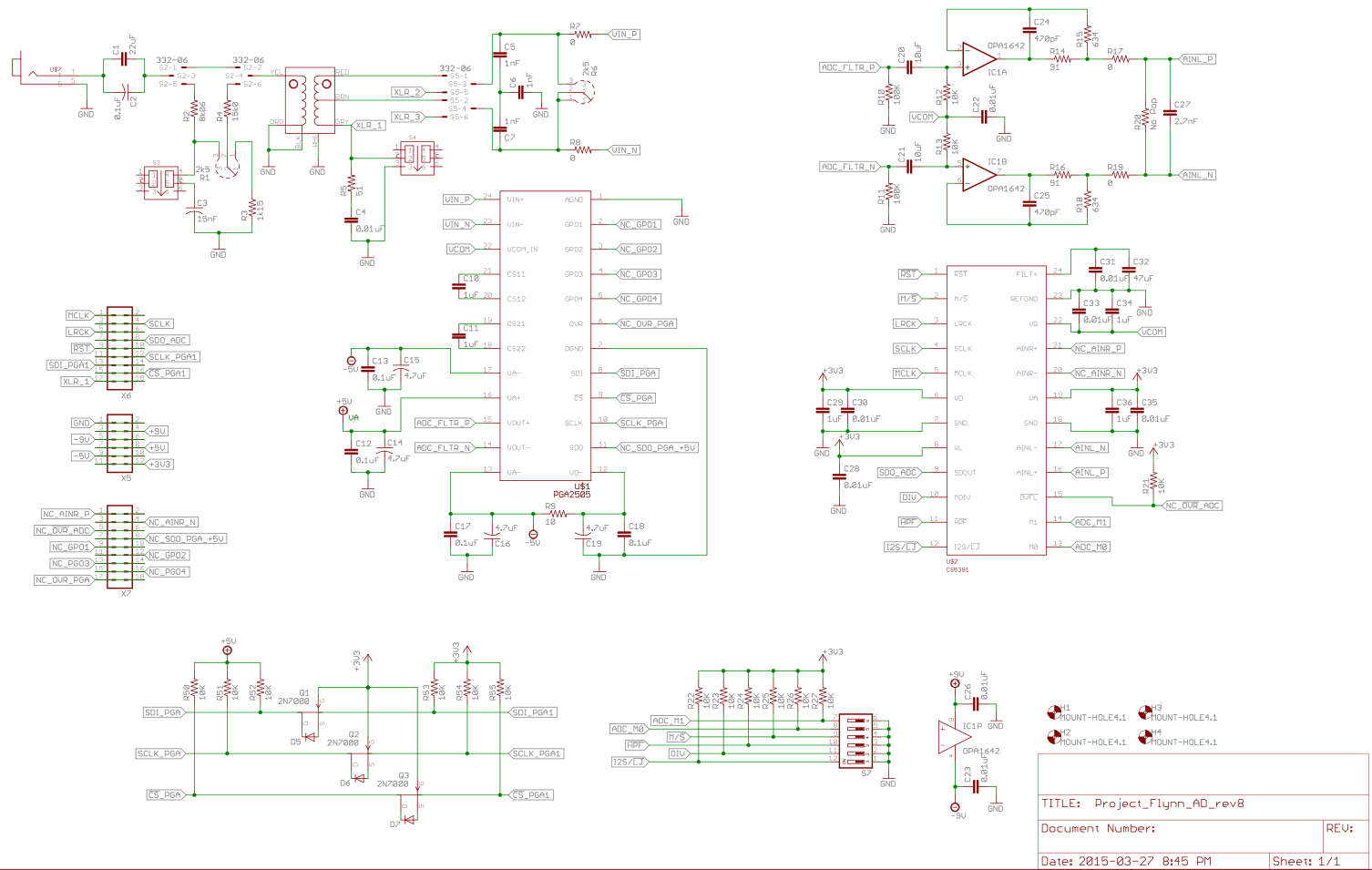
The design begins with a passive, direct input stage. This stage must provide high input impedance, and convert a single-ended (unbalanced) signal, typical of a guitar input, to differential signal suitable for the analog-to-digital (ADC) stage. The design was based on a design provided by Jensen for their JT-DB-E Direct Box Application Schematic. The input stage included a variable and switchable attentuation pad with a high-cut filter switch. An audio transformer was utilized to balance the input signal and provides a 12:1 step down, suitable to input to a microphone preamplifier. It also provides Faraday shielding to minimize noise. The transformer also provides a very high input impedance, roughly a 10:1 impedance ratio for the output impedance of a typical wound guitar pickup. The high impedance ratio reduces signal reflection and guarantee a high quality input signal. Additionally, a ground lift was implemented, to optionally help eliminate ground loop hum which may occur in certain situations.
Preamplifier
A Texas Instruments PGA2505 digitally controlled microphone preamplifier IC was used to amplify the signal to an appropriate level, maximizing the signal-to-noise ratio in the digital domain. This also allows a microphone-level XLR connection to be switched into the circuit. The preamplifier stage is controlled by the microprocessor via SPI, controlling the gain.
A/D Input Buffer
A full differential operational amplifier was employed for conditioning the signal to be suitable for the A/D converter. The design employed was based on the recommended circuit provided by Cirrus Logic for the CS5381 A/D converter (DS563F2). This circuit provides a DC offset such that signal is suitable for the A/D 0 to 5 V input (centered at 2.5 V). It also limits the peak voltage of the input signal to 5 V.
The TI OPA1641 op amps were chosen to implement this circuit due to their high quality and suitability for audio applications with their high slew rate.
A/D and D/A Stages
The Cirrus Logic CS5381 and CS4398 delta-sigma converters were used for the A/D and D/A stages, respectively. These companion ICs provide up to 192 kHz sampling rate with 24-bit depth. They communicate with the microprocessor via I2S serial audio communication. Even though only a mono input was implemented for our prototype, in the future the input and/or output hardware stages could be modified for stereo audio allowing for stereo effects to be employed with these converters.
The CS5381 comes equipped with a built-in digital anti-alias filter, removing the need for an external anti-aliasing filter on the input.
Output Stage
Following the DAC, the signal is passed through another fully differential buffer/low-pass filter circuit to a 1:1 output transformer that converts the signal from differential to unbalanced. The buffer circuit was modeled after the differential low-pass filter circuit in Cirrus Logic’s DS568DB1 evaluation board schematic. The output circuit was designed after the JT-11P-1 Balanced Line Level to Unbalanced Guitar Level Converter by Jensen. The output transformer also assists in reducing noise in the signal by decoupling the output from the rest of the circuit.
User Interface
The user interface consisted of two rotary encoders with LED ring feedback and an LCD screen. Each encoder interfaced with the microprocessor via two GPIOs for rotation information, encoding changes in the position via Gray Code, and a third GPIO for the push button. One of the benefits of rotary encoders is that they do not have a rotational limit and encode information based on relative changes instead of an absolute position. This circumvents issues commonly found with potentiometers in digital applications where recalling parameter presets can’t actually modify the position of the potentiometers, leading to confusing and unwanted behaviour. The LED rings were used to display the value of parameters configured by the user.
The push button of one encoder was used to navigate to the main menu to select the effect. The push button of the other encoder was used to give the user control of the gain on the preamplification stage (basic volume control). When an effect was selected (and the user was not modifying the input gain) the rotary encoders would allow the user to control parameters for that effect.
Digital Signal Processing
The XInC2 microprocessor by Eleven Engineering was used for the digital signal processing. It provides a digital audio serial interface (DASI) for communication with the A/D and D/A converters via I2S. The XInC2 features a hardware multithreaded architecture, i.e., does not run on an operating system. This reduces any processing overhead of context switching threads. This is a 16-bit microarchitecture, and for the sake of simplicity with prototyping, only 16-bit samples were used. It also features a vector processing unit (VPU) which implements a free running multitply and accumulate unit allowing for hardware accelerated FIR filter processing.
We had separate hardware threads executing for
- Reading from the DASI input buffer (A/D)
- Writing to the DASI output buffer (D/A)
- User Interface
- Processing Effects
Bitcrush/Downsampler
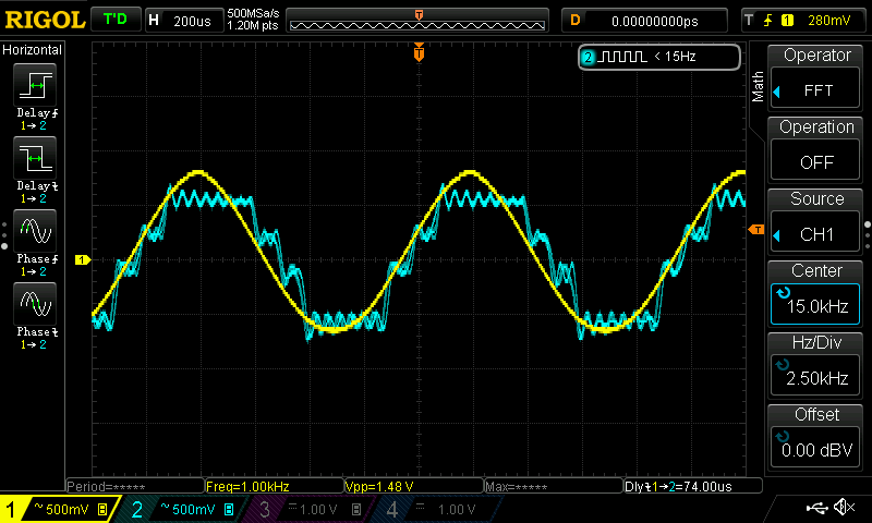
One of the effects implemented was a very simple bitcrush and desampler effect. One parameter controlled the truncation of the input samples, allowing varying the signal from clean, to something resembling retro video game consoles. The other parameter controlled an artifical downsampling of the input, resulting in heavy aliasing artifacts being introduced and generating some extreme distortion.
Hard-gate Tremolo
Another effect was the ‘Kill Switch’ effect. The input signal is simply modulated with a square wave envelope. The two parameters control the frequency and the duty cycle of the envelope.